Designing Counter Die Relief Profiles for Laminated Folding Boxboard
Counter die relief profiles for film laminated folding boxboard require expanding channel widths by twenty percent to prevent outer film shear tearing.

Geometry
Platen die cutting of laminated cartonboard requires exact male creasing rule clearances to protect outer plastic films from excessive strain. When a rule forces a multi-ply sheet into a counter slot, the exterior film undergoes severe tensile stretching. Standard boxboard calculations assume symmetric strain distribution around the central axis of the sheet, but applied polymer films shift this axis outward, increasing strain across the score line.
Channel width and depth must be adjusted to accommodate this extra bulk without causing surface shear or film rupture.
Calculating Channel Dimensions for Film Laminated Board
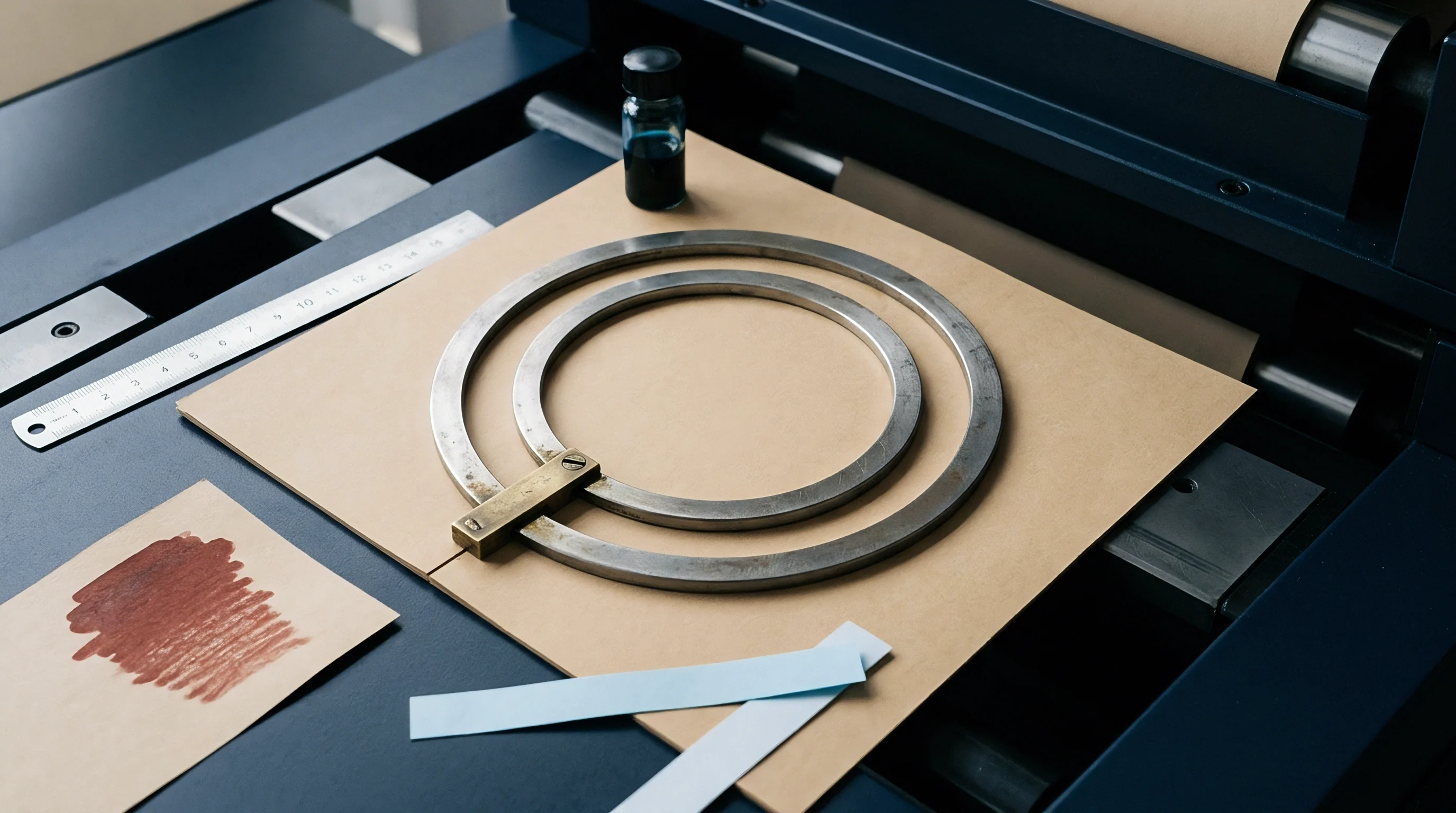
Substrate thickness alone does not dictate the channel width required in a counter plate. The polymer film adds stiffness and alters how paperboard fibers yield during folding. For unprinted folding boxboard, channel width typically equals male rule thickness plus 1.5 times board caliper.
Adding a film lamination pushes this multiplier up to 1.7 or 1.9, depending on the polymer chemistry and adhesive thickness.
For example, take a 400-micron folding boxboard substrate laminated with 15-micron biaxially oriented polyethylene terephthalate film and a 3 gsm polyurethane adhesive layer, giving a composite thickness of 0.418 millimeters. Paired with a 2-point male creasing rule (0.71 millimeters wide) and applying a 1.8 multiplier for the film, the target channel width is 0.71 plus 1.8 times 0.418, or 1.46 millimeters. Standard unprinted board of the same caliper would use a 1.34 millimeter channel.
Omitting this 0.12 millimeter allowance increases surface tension beyond the yield limit of the adhesive.
A 12-micron metallized polyethylene terephthalate lamination increases required channel width by 0.08 millimeters over unprinted board at 23 degrees Celsius and 50 percent relative humidity.
Channel depth requires similar precision. While standard practice sets channel depth equal to board caliper for unprinted grades, film-laminated board requires a depth allowance between 100 percent and 105 percent of total sheet caliper to compress the fiber matrix without overstretching the outer film. Excessive depth produces loose, undefined score lines that fail to square properly on automated packing lines.
Creasing Rule Profile Selection and Shoulder Bevels
Blade geometry determines how mechanical pressure transfers into the multi-ply board structure. Standard creasing rules feature a rounded radius tip, which pushes the plastic film smoothly into the channel and distributes elongation across a broader arc. A sharp or narrow tip concentrates force along a thin line, causing instant film splitting.
Rule height must match platen cutting height within 0.01 millimeters across the entire chase to prevent localized over-compression.
Beveling the channel shoulders further reduces shear stress at the entry point. Milling a 30-degree to 45-degree chamfer along the top edge of the counter channel creates a lead-in ramp for the board, preventing the sharp upper corner of the counter plate from acting as a secondary cutting edge. Chamfer depth usually extends 0.10 millimeters below the counter surface, relieving stress where the outer film bends into the channel.
Inadequate channel clearance forces the polymer film past its ultimate tensile elongation, leading to press stoppages and rejected pallets at the folder-gluer.
Delamination
Platen pressure causes deep cross-sectional deformation along the crease line. As the male rule drives into the sheet, internal fiber layers separate along natural cleavage planes while the exterior film stretches over the tool profile. Folding boxboard consists of a high-density bleached chemical pulp top liner, a low-density mechanical pulp middle layer, and a chemical pulp back liner.
Adding a non-porous polymer layer bonded with polyurethane adhesive alters how these distinct plies shift and absorb bending energy.
Interlaminar Shear Stresses during Male Rule Penetration
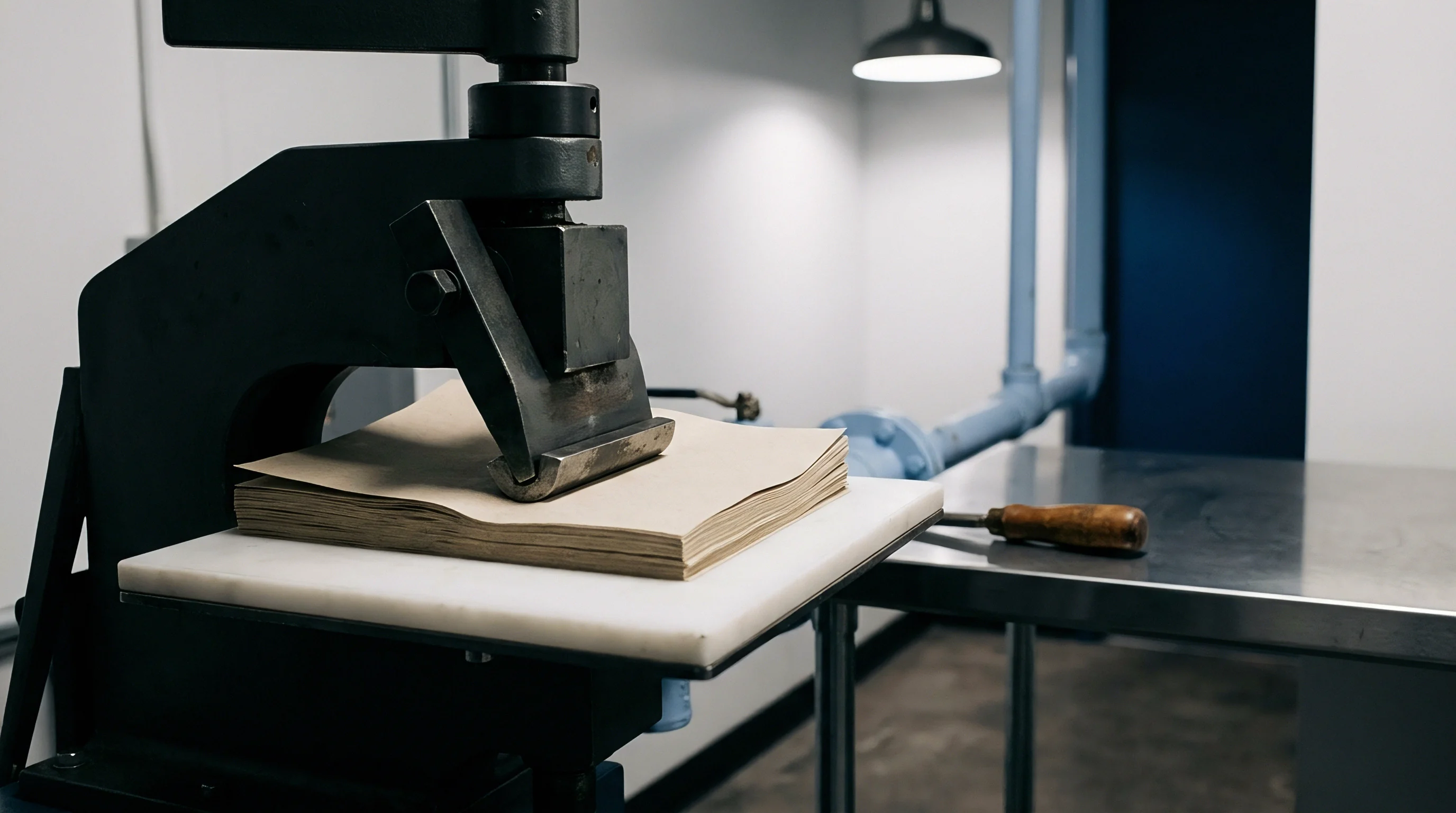
Force from the steel rule drives board fibers downward while drawing adjacent surface layers sideways. The outer film acts as a tension membrane, resisting longitudinal stretch and shifting maximum shear stress directly into the adhesive interface and underlying top liner. If adhesive bond strength exceeds the internal bond strength of the paperboard, the fiber layer immediately beneath the print face delaminates.
If the adhesive has low shear strength or incomplete curing, the film lifts from the board, forming milky blisters along the crease edge. These become visible immediately after die cutting or during panel folding on high-speed folder-gluers. Proper channel profiling controls these shear forces by giving board fibers room to bulge laterally without trapping the film under extreme compressive shear.
Film Polymer Elongation Limits and Adhesive Interface Failure
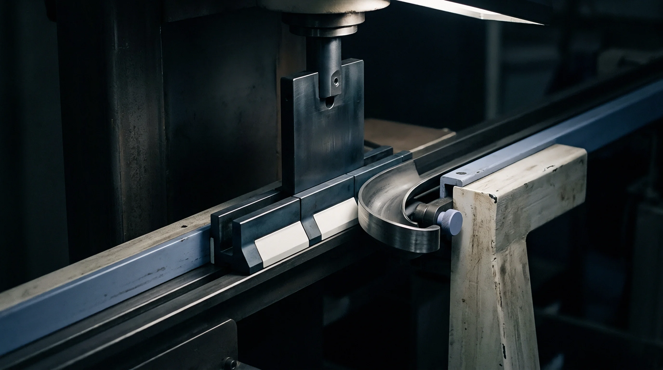
Lamination films have distinct ductility limits under dynamic impact. Polypropylene films tolerate 100 to 180 percent elongation before failure, offering broad operational latitude during creasing. Polyethylene terephthalate films feature a higher tensile modulus but lower elongation, failing at 60 to 100 percent strain.
Cellulose acetate films have low tear resistance and require wider counter channels to prevent splitting along the crease line.
| Film Polymer Type | Nominal Film Thickness (microns) | Lamination Adhesive Base | Yield Elongation Limit (percent) | Channel Clearance Multiplier |
|---|---|---|---|---|
| Biaxially Oriented Polypropylene | 12 to 18 | Water-Based Acrylic | 140 to 180 | 1.70 |
| Polyethylene Terephthalate | 12 to 15 | Solventless Polyurethane | 70 to 100 | 1.85 |
| Metallized Polyethylene Terephthalate | 12 | Solvent-Based Polyurethane | 60 to 85 | 1.95 |
| Cellulose Acetate | 14 to 20 | Wet-Laminated Starch Acrylic | 35 to 50 | 2.10 |
Compliance with DIN 55437 testing for creasing behavior dictates that board thickness calculations include all film adhesive layers before die fabrication.
Adhesive failure modes vary by chemistry: water-based acrylics undergo plastic flow under impact, whereas cured polyurethanes behave elastically and transmit peak impact forces directly into the top liner. Counter die profiles must accommodate this rigidity by opening the relief shoulder geometry to lower peak force concentration at the outer channel boundary.
Measuring real-time micro-fracturing along the adhesive interface during high-speed platen impact remains an unresolved technical challenge in converting.
Pertinax
Machined phenolic resin counter plates provide the stability needed for consistent creasing channel geometry. Phenolic paper laminates (commonly called pertinax) resist dimensional change under heavy compressive loading while supporting high-precision CNC milling. Steel counter plates offer longer impression life, but lack the rapid custom relief milling flexibility required for complex, short-run film-laminated jobs.
Which Milling Cutter Geometry Yields Clean Counter Relief Shoulders?
High spindle speeds combined with specific carbide fluting prevent thermal melting along channel edges. Milling pertinax counters typically involves single-flute or two-flute micro-end mills operating between 40,000 and 60,000 RPM. Single-flute tools clear resin dust efficiently, avoiding the frictional heat that can weld swarf back onto shoulder walls.
Clean channel walls are essential when creasing laminated boxboard. Any roughness, micro-burr, or chatter mark along the wall snags the stretching film during platen closure, creating localized stress that causes tearing or edge whitening. Technicians inspect milled channels under optical magnification before mounting counters to the cutting plate.
- Resin burr formation along channel shoulders catches surface film and initiates localized tearing during high-speed feeding.
- Channel wall taper from end mill wear alters effective groove width over the production run.
- Adhesive backing lifting caused by milling heat leads to counter plate displacement under platen tonnage.
- Relief pocket depth variance creates unequal compression across adjacent panel scores, distorting carton geometry.
Softer lamination films require wider counter relief channels to absorb plastic deformation without tearing adjacent board fiber.
CNC Milling Depth Tolerances and Relief Pocket Routing
Recessing non-creasing areas reduces overall platen resistance and stops secondary surface crushing across the printed sheet. Relief pockets are milled into the pertinax plate around cut lines, embossed regions, and reverse-fold scores. Standard relief depth for non-creasing pockets spans 0.30 to 0.50 millimeters below nominal counter height, with a milling depth tolerance of plus or minus 0.005 millimeters to maintain plate rigidity.
When routing relief areas next to creasing channels, the tool path leaves a narrow land to support the sheet flat as the male rule enters the groove. On film-laminated boxboard, narrowing this land below 1.2 times board caliper lets the sheet sink into the relief pocket, resulting in an asymmetric, skewed crease.
Minor shoulder fuzz on milled counter channels often vanishes after five hundred press impressions under operational heat and pressure.
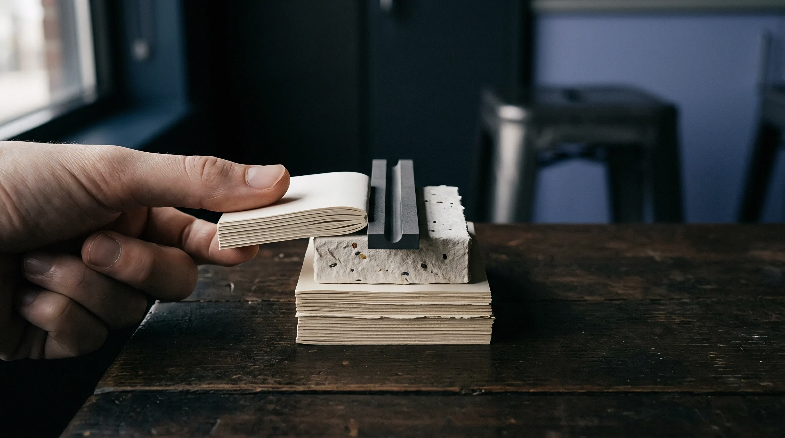
Groove
Press operators calibrate counter plate positioning using carbon paper strikes and micro-thin steel shims. Registration between the steel creasing rules in the chase and the milled pertinax channels on the cutting plate must be exact. A misaligned channel forces the male rule against one side wall, crushing board fibers on one edge while leaving excess space on the other ~ an eccentricity that quickly tears the film along the pinched edge.

Platen Press Make-Ready Calibration and Impression Tuning
Establishing uniform tonnage across the die face requires balancing counter thickness against platen parallelism. Make-ready begins with zero-pressure registration checks using carbon sheets, where the impression pull highlights localized pressure spikes across the sheet layout. Technicians apply paper or steel make-ready tape beneath the cutting plate to adjust individual sections and bring all creasing channels into equal mechanical contact.
Localized pressure spikes force male rules too deep into pertinax channels, crushing the paperboard core and snapping the film lamination.
- Verification of plate bedding eliminates dirt or oil beneath the lower cutting plate before mounting milled pertinax counters.
- Carbon sheet impression pull identifies pressure variances across the die layout under minimal platen tonnage.
- Gradual tonnage advancement brings creasing rules into full contact without over-compressing the phenolic counter matrix.
- Bending stiffness evaluation verifies that folded scores achieve the targeted moment reduction without film fracture.
Standard practices specify a 1.8 channel width multiplier for 15-micron PET laminates based on 150 mm/min creasing speed tests, though raising line speed to 300 meters per minute increases the required multiplier to 1.95 due to dynamic strain hardening. Because standard test data for the shear modulus of water-based acrylic adhesives under high strain is limited, converters mitigate risk through pre-production drawdown trials across extreme channel widths.
Milled resin counter plates lose structural depth accuracy when ambient press room humidity shifts across extended production shifts.

Crease Moment Measurement and Structural Bending Resistance
Automated packaging machinery demands predictable score resistance for rapid folding without panel distortion. Crease stiffness testing measures the bending moment required to rotate a scored panel through 90 degrees. While unscored board generates high bending resistance, a properly creased laminated sheet shows a 50 to 70 percent reduction in bending moment compared to the uncreased substrate.
| Substrate Caliper Range (microns) | Rule Width (pt) | Base Channel Depth (mm) | Recommended Width (mm) | Relief Chamfer Angle (degrees) |
|---|---|---|---|---|
| 250 to 300 | 1.5 | 0.28 | 1.05 | 30 |
| 300 to 400 | 2.0 | 0.38 | 1.45 | 35 |
| 400 to 500 | 2.0 | 0.48 | 1.65 | 45 |
| 500 to 600 | 3.0 | 0.58 | 2.10 | 45 |
| Calculations assume 23 degrees Celsius, 50 percent relative humidity, and 2-point rule thickness. | ||||
Adjusting counter relief profiles directly alters this bending moment. Narrowing the channel increases internal fiber fracture, which lowers bending resistance but raises the risk of film rupture. Widening the channel protects the film, but leaves more of the paperboard core intact, resulting in higher residual stiffness.
Converters balance these trade-offs to meet packaging specifications without causing aesthetic score failure.
- Substrate and film characterization data specifying board caliper, fiber orientation, polymer film type, and adhesive coat weight.
- Precision counter material certification documenting phenolic sheet thickness uniformity, density tolerances, and surface flatness.
- First-off inspection protocol outlining optical magnification checks for score cracking, film whitening, and adhesive separation.
- Replacement channel threshold criteria establishing allowable dimensional counter wear before tool replacement during production.
Smooth crease lines without film whitening indicate balanced channel geometry and a stable adhesive bond.
Tolerance
Establishing clear dimensional tolerances for scoring channels protects converting plants from costly rejections. Precision die making operates within tight margins, where small deviations in rule thickness, counter depth, or channel alignment accumulate into defects. Laminated folding boxboard amplifies these sensitivities because of the exterior film’s stiffness, making consistent tool tolerances critical on high-speed runs.
Quality Control Specifications and Score Cracking Limits
Visual inspection under 5x magnification catches micro-fractures before finished cartons reach packaging lines. Defects range from subtle film stress whitening to complete rupture and exposed fiber. Quality specifications require continuous film integrity along the full length of the crease; any gap invalidates barrier performance, exposing the substrate to moisture and oil.
Automated inspection systems mounted on folder-gluers monitor crease quality at full line speed. High-resolution line-scan cameras detect specular reflections from cracked film or delaminated blisters. When defects cross statistical thresholds, the system automatically ejects the carton without interrupting production.
Setting realistic rejection limits prevents unnecessary scrap while maintaining compliance for pharmaceutical and food packaging.
Commercial Risk Allocation in Tooling and Material Waste
Disputes over defective folds usually center on whether substrate variation or tool geometry caused the failure. Paperboard mills supply board within defined caliper ranges, typically plus or minus 5 percent of nominal. A positive caliper spike on a laminated sheet increases compressive stress inside a fixed counter channel, causing instant splitting.
Conversely, undersized board produces inadequate fiber deformation, leading to distorted cartons.
Clear tooling specifications assign commercial responsibility based on physical measurements taken before press setup. Converting contracts specify counter channel dimensions for given board-film combinations. When running certified board through verified counter profiles, liability for score cracking shifts to the substrate supplier if material caliper or internal bond strength deviates from technical datasheets.
Standard delivery contracts incorporating DIN 55437 clause 4.2 transfer financial liability for score cracking to the converting mill whenever counter die relief dimensions deviate from agreed structural files.