Dynamic Platen Impression Adjustments for High-Speed Multi-Ply Creasing Operations
Dynamic platen impression adjustment balances platen bow and speed-dependent viscoelastic strain to eliminate liner cracking in multi-ply cartonboard.

Delamination
Folding boxboard exhibits layered mechanical behavior when subjected to perpendicular compressive forces from sharp steel rules. Multi-ply substrates consist of distinct pulp layers, including bleached chemical pulp outer liners and mechanical pulp middle plies, engineered to maximize bending stiffness while keeping sheet weight low. When a creasing rule impacts the board during high-speed platen motion, local stresses concentrate sharply in the substrate.
Successful crease formation depends on localized internal ply separation along predefined shear planes without rupturing either liner layer.
The structural geometry of multi-ply virgin folding boxboard (FBB) and coated recycled board (CRB) governs how forces propagate through sheet thickness during die penetration. Mechanical forces from the upper platen drive the creasing rule tip into the top liner, forcing material down into the female channel resting on the bottom impression bed. This displacement induces out-of-plane tensile stress and in-plane shear stress between adjacent fiber networks.
Under high compressive loads, ply bond strength dictates whether multi-ply cartonboard shears smoothly inside the creasing channel.

Mechanics of Score Line Bead Formation
Penetration of a rounded steel profile into multi-ply paperboard creates localized shear stresses along inner fibrous networks. As the rule descends, the top liner deforms plastically while middle mechanical plies delaminate along internal interfaces. This controlled delamination forms the flexible hinge structure known as the score bead.
Without internal ply separation, the board acts as a solid monolithic beam, forcing the outer liner to stretch past its ultimate strain limit during subsequent ninety-degree or one-hundred-and-eighty-degree folding operations.
Liner cracking occurs when excessive platen impression force crushes the middle plies completely flat, eliminating the internal airspace that delaminated plies need to buckle outward cleanly. Conversely, insufficient platen pressure fails to initiate middle ply separation, leaving tensile strain concentrated on the reverse side of the board. Converting lines running at seven thousand to ten thousand sheets per hour compound this challenge because load duration drops sharply.
At high cycling frequencies, cellulosic fibers display a higher elastic modulus and reduced stress relaxation, making precise impression depth essential to prevent liner fracture.
Scott bond strength below one hundred eighty Joules per square meter triggers uncontrolled ply separation when creasing rule penetration exceeds sixty-five percent of board caliper.
Ply Bond Strength and Internal Delamination Resistance
Measuring Z-direction tensile forces according to ISO 15754 defines how individual fibrous plies separate during high-speed converting. Internal bond strength, measured via the Scott Bond test (TAPPI T 569), records energy absorbed per unit area during high-velocity impact delamination. Recycled boards often exhibit uneven internal bond profiles compared to solid bleached sulphate (SBS) boards.
This variance changes the exact mechanical impression tonnage needed to form uniform beads across the entire platen surface.
When converting multi-ply liquid packaging board (LPB) containing polymer and aluminum barrier films, internal delamination mechanics become critical. Polyethylene film layers resist localized elongation, transferring shear forces back into the fiber core. If the platen impression setting is too tight, the polymer film tears along the creasing shoulder and breaks the barrier.
If it is too loose, the thick middle plies resist deformation, creating high folding resistance that jams cartoning machines downstream.
The table below summarizes typical multi-ply board grades, their internal bond characteristics, and target creasing channel parameters under nominal converting conditions.
| Substrate Grade | Caliper Range (mm) | Scott Bond Range (J/m²) | Rule Thickness (pt / mm) | Channel Width Ratio | Target Impression Penetration (% Caliper) |
|---|---|---|---|---|---|
| Solid Bleached Board (SBB) | 0.30 – 0.60 | 200 – 350 | 2 pt / 0.71 mm | 1.4 x Caliper + Rule | 45 – 55% |
| Folding Boxboard (FBB) | 0.35 – 0.80 | 140 – 220 | 2 pt / 0.71 mm | 1.5 x Caliper + Rule | 50 – 60% |
| Coated Recycled Board (CRB) | 0.40 – 0.85 | 110 – 170 | 3 pt / 1.05 mm | 1.7 x Caliper + Rule | 55 – 65% |
| Liquid Packaging Board (LPB) | 0.45 – 0.90 | 180 – 260 | 3 pt / 1.05 mm | 1.6 x Caliper + Rule | 40 – 50% |
| Micro-Flute (N/F Flute) | 0.60 – 1.20 | N/A (Flat Crush) | 3 pt / 1.05 mm | 1.8 x Caliper + Rule | 60 – 70% |
Substrate density variations across paperboard batches shift mechanical requirements at the cutting nip. Higher-density board requires higher peak forces to initiate delamination, but excessive force crushes the score shoulder, weakening the score line. Setting impression clearance based solely on nominal board thickness leads to high rejection rates over long production runs.
Misjudging the internal bond resistance of multi-ply board during press setup leads to incorrect impression depth that crushes internal fibrous structures, destroying carton stiffness and triggering automatic rejects on folder-gluer lines.

Wedge
Motorized bed leveling systems on automatic platen presses adjust upper and lower beam clearance in five-micrometer increments. Positioned between the main drive toggles and the lower bed plate, these wedge mechanisms provide fine axis and quadrant adjustments across the cutting surface. Modern high-speed automatic die-cutters rely on dynamic wedge control to offset mechanical bed deflection, frame strain, and thermal expansion during continuous production runs.
As press speeds rise from two thousand sheets per hour during setup to over eight thousand sheets per hour in production, dynamic forces stretch the cast iron press frame. Bending loads on the upper platen and lower bed reach several hundred metric tons of peak force per stroke. Creasing multi-ply board requires extreme impression stability across the full format width, as a variation of just fifteen micrometers in clearance alters bead height enough to crack liners or impair folding performance.

Thermal Bowing and Bed Deflection Profiles
Temperature shifts over long production runs cause microscopic expansion across cast steel frames. Friction in the main driving toggles and eccentric shafts transmits heat into the lower platen. Because heat distribution across large platen surfaces is rarely uniform, center regions run warmer than outer frame edges, creating a crowned thermal profile across the bed.
This expansion narrows the central clearance gap while outer quadrants retain their cold setup dimensions.
Multi-ply board creasing is exceptionally sensitive to this central crown. Without active correction, central die positions suffer excessive penetration that crushes internal plies and splits liners along long score lines. At the same time, outer die positions receive shallow creasing that fails to delaminate the sheet.
Modern automatic presses counter this thermal drift with motorized multi-wedge systems that adjust lower bed quadrants independently while running at full rated speed.
Dynamic thermal expansion of the impression bed during morning ramp-up alters effective crease depth across large format platens.
The mechanical factors contributing to uneven platen impression profiles include several distinct machine and material interactions:
- Toggle Joint Deflection under peak tonnage generates a parabolic deflection curve along the longitudinal platen axis, shifting maximum impression clearance toward the exact bed center.
- Thermal Gradient Expansion creates dimensional bed growth up to forty micrometers between cold make-ready state and steady-state operating temperature across eight-hour shifts.
- Die Chase Torsional Twist under asymmetrical rule density distorts the steel cutting plate surface, forcing localized impression pressure variances across multi-up carton layouts.
- Counter Plate Thickness Tolerances contribute cumulative height variations that alter localized creasing rule penetration depths across individual carton blanks.
- Substrate Moisture Regain Shifts during storage alter board thickness and elastic modulus, requiring real-time wedge position compensation during run execution.

Servo Motorized Pressure Segment Corrections
Modern automated die-cutters divide the impression zone into four quadrant drives capable of independent micro-stepping. Precise servo motors drive inclined steel wedges beneath each corner of the impression bed plate. When the system detects asymmetric tonnage or thermal growth, the drives advance or retract the wedge profiles, raising or lowering bed segments in increments as fine as two micrometers.
Evaluating dynamic load distributions across six-up formatting shows that wedge bed adjustments offset bed bow by up to forty micrometers. This dynamic intervention eliminates traditional manual tissue patching and paper shimming beneath the counter plate during production. Operators make real-time impression adjustments from the machine console without stopping the feeder or opening the main safety enclosure.
The following table illustrates the calculated dynamic tonnage adjustments and wedge clearance corrections required across press speed stages to maintain constant crease bead compression on a hundred-and-forty-centimeter flatbed platen press.
| Operating Speed (sheets/hr) | Peak Tonnage (Metric Tons) | Center Bed Bow (µm) | Thermal Expansion Delta (µm) | Servo Wedge Correction Offset (µm) | Effective Crease Depth Delta (µm) |
|---|---|---|---|---|---|
| 1,500 (Setup) | 120 | +5 | 0 | 0 (Base Reference) | 0 |
| 4,000 | 180 | +14 | +6 | -12 | +2 |
| 6,000 | 230 | +22 | +14 | -24 | +3 |
| 8,000 | 280 | +31 | +25 | -38 | +1 |
| 9,500 (Max Speed) | 315 | +40 | +36 | -52 | 0 |
Dynamic impression control maintains constant mechanical penetration depth even as press frame deflection doubles under high cycling loads. By correlating press speed, operating temperature, and board caliper measurements, automated wedge systems prevent line stoppages caused by inconsistent crease quality.
While automated wedge leveling systems reduce overall make-ready paper patching, local steel die tolerances and localized counter wear still demand manual foundational shimming before automated leveling loops take effect.

Counter
Female channel dies milled into pre-stretched steel plates maintain rigid groove boundaries under continuous cyclic loading. The counter plate acts as the opposing tool to the male creasing rule, forcing multi-ply board into the milled slot to form the score bead. Choosing appropriate counter plate materials, channel widths, and channel depths determines whether cartonboard undergoes precise internal delamination or localized structural shear failure.
In high-speed folding boxboard converting, precision steel counters milled on specialized CNC routing centers have largely replaced traditional vulcanized fiber and pressboard matrix strips. Milled steel plates offer superior dimensional stability, keeping channel width constant within plus or minus three micrometers across millions of impression cycles. Any channel widening during a run reduces compressive force on the board shoulders, producing shallow score beads and unstable folding performance.
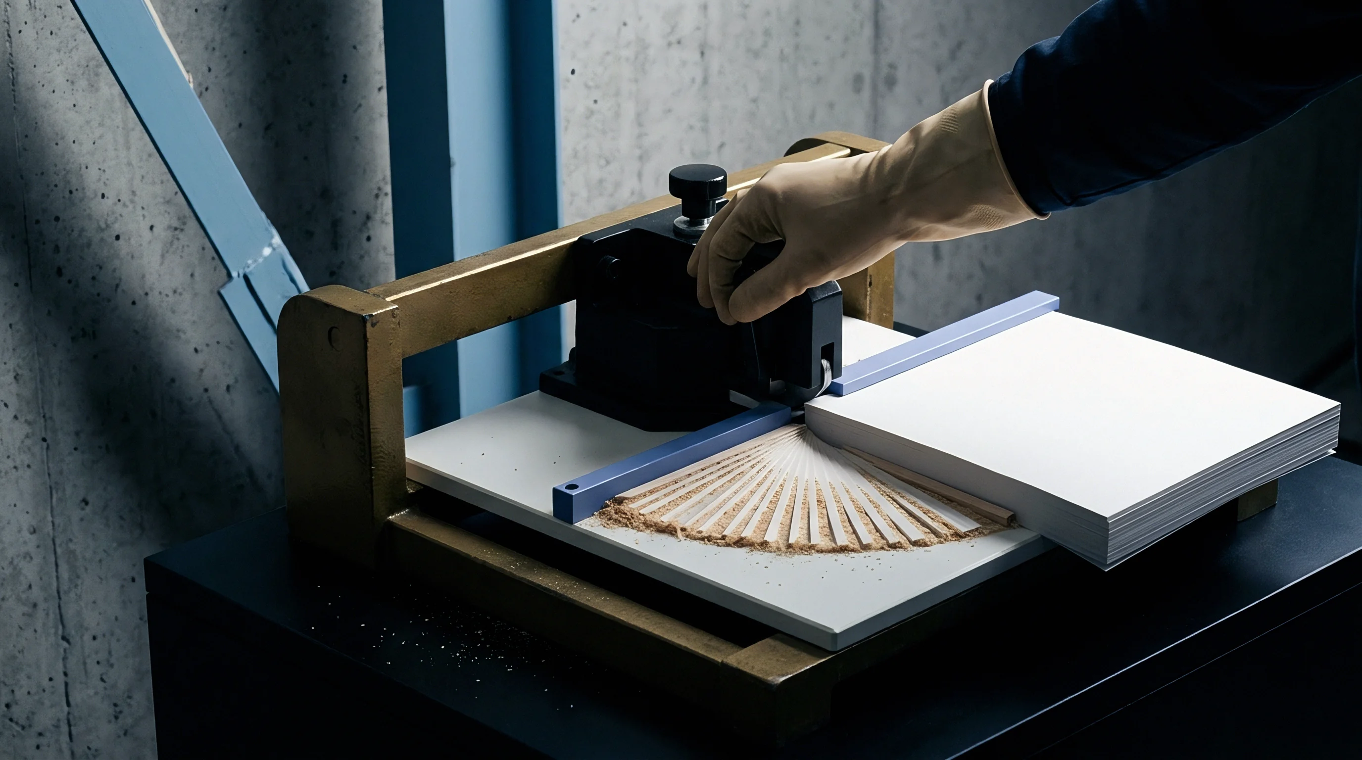
Channel Geometry for Laminated Multi-Ply Grades
Calculating channel width using standard formulas requires distinct adjustment factors when polymer film covers the top liner. For unlaminated cartonboard, standard channel width equals one rule thickness plus one point five times total board caliper. However, when converting glossy polyethylene or metalized PET laminated boards, the outer film layer resists immediate shear stress release.
The film acts as a tension membrane, requiring a wider channel geometry to prevent surface scoring and film rupture.
Channel depth selection demands equal care. If depth is less than nominal board caliper, the descending creasing rule crushes the score bead flat against the bottom of the milled groove, destroying the internal delamination airspace. Conversely, if the channel is too deep, the board lacks bottom support during the impression stroke, preventing the reverse liner from stretching properly around the creasing rule edges.
Creasing channel width adjusts with substrate tensile stiffness rather than total board thickness alone when converting multi-ply recycled grades.
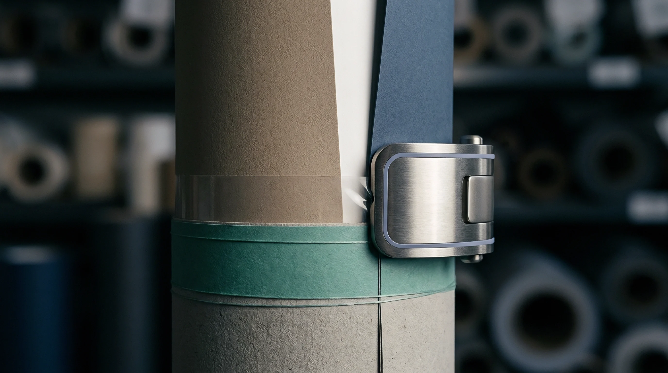
Wear Rate Comparatives across Die Materials
Phenolic matrix strips compress during initial production, losing depth accuracy within thirty thousand impressions. As matrix walls deform laterally under repeated side loads from descending rules, channel width expands, altering the force balance on the substrate. Milled steel counter plates eliminate this lateral displacement, preserving accurate score profiles over runs exceeding five hundred thousand impressions.
To establish proper steel counter plate installation and verify alignment across high-speed die-cutting presses, setup engineers execute a structured mechanical validation sequence.
- Mount the primary die chase into the upper platen structure and lock mechanical clamps to eliminate lateral chase play.
- Clean the lower impression bed surface thoroughly using solvent cleaners to remove oil film and particulate debris.
- Position the milled steel counter plate onto the impression bed plate using high-precision locator pins to secure register alignment.
- Apply pressure-sensitive adhesive tape along counter plate boundaries to secure edge positioning during dynamic pressure ramping.
- Execute a low-speed dry impression stroke at one thousand sheets per hour to verify rule-to-channel centering across all layout positions.
- Measure female groove clearance using optical depth gauges at four peripheral and two central matrix positions.
- Increase press cycling speed in increments of two thousand sheets per hour, recording dynamic crease bead height at each speed plate.
Selecting counter materials requires balancing upfront tooling costs against expected run lengths and carton quality standards. The following table provides comparative operational metrics for common counter matrix technologies.
| Counter Material Type | Shore Hardness / Elastic Modulus | Dimensional Depth Tolerance (mm) | Useful Impression Life (Sheets) | Channel Wear Rate (µm per 100k sheets) | Tooling Cost Factor (vs Matrix) |
|---|---|---|---|---|---|
| Pressboard Matrix Strips | 85 Shore D | ±0.030 mm | 15,000 – 35,000 | 35 µm | 1.0 x |
| Phenolic Resin Counters | 95 Shore D | ±0.015 mm | 80,000 – 150,000 | 12 µm | 3.5 x |
| Elastomeric Polymer Plate | 70 Shore D | ±0.020 mm | 50,000 – 100,000 | 18 µm | 2.8 x |
| Milled Mild Steel Plate | 210 GPa Modulus | ±0.005 mm | 500,000 – 1,200,000 | 2 µm | 7.0 x |
| Hardened Stainless Steel | 230 GPa Modulus | ±0.003 mm | 2,000,000+ | <1 µm | 11.0 x |
Improper counter channel geometry during multi-ply board converting creates excessive score stiffness, forcing downstream folder-gluers to apply higher side-belt pressure that marks sensitive printed surfaces.
As an operational guideline, counter channel width must scale directly with cross-direction stiffness whenever board stiffness increases by more than fifteen percent above nominal mill specifications.
Velocity
Accelerating press speed from mechanical inching to nine thousand sheets per hour alters board deformation behavior. Cellulosic fibers are viscoelastic materials, exhibiting time-dependent mechanical properties when subjected to dynamic strain rates. At slow setup speeds, extended dwell time allows polymer chains within wood fibers and starch adhesives to relax under compressive stress.
At full production speeds, dwell time inside the impression nip drops to milliseconds, sharply increasing effective board stiffness.
In high-speed multi-ply creasing, score lines established during slow make-ready frequently crack or split open as soon as the press accelerates to full production speed. This occurs because high strain rates increase the peak stress needed for plastic deformation. Achieving the exact internal delamination bead depth produced during slow setup requires higher dynamic forces from the platen system.
Viscoelastic Response under High Strain Rates
Cellulosic fibers require a few milliseconds to realign and deform permanently under mechanical impact. During high-speed dynamic impression, available time for fiber displacement drops sharply. At three thousand sheets per hour on a standard flatbed press, impression dwell time at bottom dead center is approximately twenty-five milliseconds.
When operating speed reaches nine thousand sheets per hour, dwell time drops below eight milliseconds.
This reduction in dwell time shifts how energy dissipates within the paperboard substrate. Instead of yielding smoothly across inter-fiber bonds and internal plies, the board responds elastically, storing compressive energy without developing permanent score bead deformation. Restoring proper delamination at high cycling rates requires closing the platen clearance by several micrometers, raising peak compression force to offset shortened load duration.

How Does Machine Speed Alter Crease Channel Shear?
Shortened dwell time at high cycling rates reduces stress relaxation across internal board layers. As the rounded steel creasing rule strikes the top liner at high velocity, structural inertia prevents immediate downward deflection into the female counter groove. High local shear stresses concentrate along the rule shoulders rather than spreading evenly across the intended delamination zone.
This localized stress concentration frequently breaks the outer bleached kraft liner fibers before mechanical middle plies can separate cleanly. Machine vibration and frame resonance at high press speeds also introduce microscopic positional oscillation between the upper die chase and lower impression bed. If platen alignment shifts laterally by as little as ten micrometers during impact, the creasing rule strikes the edge of the female counter channel, shearing the board along the score edge.
The graph parameters below highlight the measured interaction between cycling velocity, effective impression clearance adjustments, and score stiffness outcomes on four-hundred-micrometer folding boxboard.
| Production Velocity (sheets/hr) | Impression Dwell Time (ms) | Apparent Board Modulus (MPa) | Required Impression Adjustment (µm) | Score Bead Height (mm) | Ninety-Degree Score Resistance (mN) |
|---|---|---|---|---|---|
| 1,000 | 32.0 | 3,100 | 0 (Setup Reference) | 0.28 | 115 |
| 3,000 | 18.5 | 3,450 | -8 | 0.27 | 122 |
| 5,000 | 12.0 | 3,800 | -16 | 0.26 | 130 |
| 7,000 | 9.2 | 4,150 | -25 | 0.25 | 141 |
| 9,000 | 7.5 | 4,500 | -35 | 0.25 | 148 |
Compensating for dynamic strain rate hardening requires pre-programming impression compensation profiles into press control systems. As the machine accelerates along its speed curve, servo-driven wedge motors advance impression depth to meet the higher force thresholds of viscoelastic paperboard plies.
A technical uncertainty remains regarding whether high-velocity impression adjustments alter the long-term fatigue limit of steel creasing rules when operating continuously above nine thousand sheets per hour across multi-day production shifts.


Telemetry
Piezoelectric load washers installed beneath impression toggle joints deliver continuously sampled force profiles throughout each cycle. Real-time tonnage monitoring reveals the dynamic forces applied during die-cutting and creasing passes. These electronic sensors record force-time waveforms for every sheet pass, detecting subtle variations caused by substrate caliper shifts, board moisture spikes, or progressive tool wear.
Integrating high-speed force telemetry into converting equipment replaces manual inspection with continuous closed-loop control. Instead of discovering cracked score lines during post-press pallet audits, digital sensor networks evaluate tonnage symmetry across every quadrant during sheet impact. When tonnage distribution shifts beyond established process limits, control algorithms send immediate corrections to motorized wedge systems.

Piezoelectric Force Sensing and Bed Load Balancing
Digital transducers register asymmetrical tonnage distribution across multi-up die forms instantaneously. In high-volume folding carton production, die layouts combine cutting rules, creasing rules, and matrix scrap strike points. Because cutting rules require significantly higher force per linear millimeter than creasing rules, total impression load is rarely centered evenly across the platen midpoint.
Asymmetrical loading creates angular deflection across the main platen beams, causing the side with lighter rule density to suffer excessive impression penetration. Piezoelectric force sensors mounted in all four bed corners quantify this moment imbalance continuously. Control systems calculate the required offset and signal individual corner servo wedges to adjust specific platen quadrants, restoring parallel clearance across the entire die chase format.
DIN 55437 compliance for crease dimensions requires tolerance holds within five micrometers to prevent high-speed folder-gluer feed failures.
Closed Loop Impression Control Architectures
Automated feedback networks continuously adjust bed motor positions during speed transitions. Sensors sample platen load profiles at frequencies exceeding ten kilohertz. Signal processing hardware filters out background noise from sheet feeders, stripper boards, and delivery grippers, isolating the exact force signature produced as creasing rules penetrate paperboard plies.
When the control architecture detects an unexpected increase in peak tonnage—often caused by a sudden batch change to higher-density paperboard—it automatically opens the platen clearance gap by a calculated margin. Conversely, if total force drops due to progressive wear on matrix channel shoulders, the system steps the impression bed up in five-micrometer increments, maintaining constant score bead dimensions across multi-shift runs.
To establish continuous operational reliability across dynamic impression telemetry platforms, automated control systems execute systematic diagnostic steps during every batch cycle.
- Sensor Zero-Point Calibration executes automatically prior to sheet feeding, resetting piezoelectric load cell drift caused by ambient press room temperature swings.
- Impact Tonnage Curve Isolation isolates creasing force peaks from cutting rule impact spikes based on angular resolver position tracking across the three-hundred-and-sixty-degree platen rotation.
- Quadrant Load Ratio Calculation compares force values across four bed quadrants to detect eccentric platen tipping moments before mechanical frame distortion occurs.
- Servo Wedge Offset Signal converts load error values into digital stepping commands dispatched to motorized bed positioning actuators.
- Data Logging and Traceability Upload archives peak force, machine velocity, and wedge offset positioning to centralized quality management databases for batch validation.
Advanced telemetry platforms also incorporate non-contact optical sensors mounted near the press delivery station. Laser displacement sensors measure actual score bead height on passing sheets in real time, verifying that mechanical bed adjustments achieve the target physical deformation on the converted paperboard surface.
Standard packaging purchasing contracts routinely include quality terms stating that carton deliveries failing DIN 55437 crease profile dimensional limits by more than six micrometers face immediate batch rejection at supplier expense.

Surcharge
Uncontrolled crease depth variation leads directly to stoppages on high-speed automated packing lines. Modern packaging machinery inserts folded cartons into outer sleeves at speeds exceeding six hundred packs per minute. If folding resistance varies across individual score lines due to inconsistent impression depth, cartoning pushers misfeed, causing automatic shutdowns, damaged product, and lost overall equipment effectiveness (OEE).
In high-volume consumer packaging manufacturing, the financial cost of poor creasing quality far exceeds the simple replacement cost of damaged paperboard. Unscheduled downtime on high-speed filling lines costs brand owners thousands of Euros per hour in lost throughput. Consequently, packaging converters face strict commercial penalties, including quality surcharges, chargebacks for customer downtime, and disqualification from vendor lists when delivered cartons fail score stiffness specifications.
Make-Ready Waste Metrics and Line Efficiency
Initial press setup accounts for the largest share of unscheduled substrate scrap during converting runs. Traditional make-ready relying on manual paper shimming requires press operators to pull test sheets, inspect score lines visually or with hand calipers, apply paper tape patches beneath the cutting plate, and re-run test sheets. This iterative process consumes between forty-five and ninety minutes per setup, wasting hundreds of sheets of premium substrate during each trial run.
Automated dynamic platen leveling dramatically reduces setup time and scrap. Storing pre-calibrated tonnage and wedge positioning profiles for specific board grades in digital memory cuts setup times to under fifteen minutes. The press achieves target crease bead parameters on the second test sheet, eliminating hundreds of sheets of setup scrap and generating substantial material cost savings over annual production volumes.
Financial Tradeoffs in Tooling Selection
Investing in dynamic platen leveling changes the amortized expense profile of high-volume die-cutting tooling. While precision CNC-milled steel counter plates demand higher upfront capital than conventional matrix strips, their operational stability shortens make-ready duration and eliminates mid-run impression readjustments.
The financial ledger model below illustrates the comparative total cost per one million folding cartons converted, comparing traditional manual platen adjustment methods against dynamic servo-controlled leveling systems on multi-ply SBS board.
| Cost Component / Parameter | Manual Setup & Standard Matrix | Automated Dynamic Wedge & Steel Counter | Net Financial Variance |
|---|---|---|---|
| Initial Tooling & Counter Expense | € 850 | € 3,400 | + € 2,550 (Higher Tooling) |
| Make-Ready Duration & Labor Cost | 75 minutes (€ 187.50) | 15 minutes (€ 37.50) | – € 150.00 (Labor Saving) |
| Make-Ready Substrate Waste Sheets | 450 sheets (€ 405) | 35 sheets (€ 31.50) | – € 373.50 (Material Saving) |
| Mid-Run Quality Adjustments Stop Time | 4 stops / 60 min (€ 150) | 0 stops / 0 min (€ 0) | – € 150.00 (Uptime Saving) |
| Folder-Gluer Jam Spoilage Rate | 0.85% (8,500 cartons) | 0.08% (800 cartons) | – € 1,386.00 (Waste Saving) |
| Customer Quality Surcharge Exposure | € 2,500 Risk Allowance | € 0 (Zero Defect Target) | – € 2,500.00 (Risk Mitigation) |
| Net Conversion Expense per 1M Cartons | € 4,092.50 + Base Run | € 3,469.00 + Base Run | – € 623.50 Net Saving |
Investing in automated platen control systems delivers clear commercial returns across long production runs. Reduced substrate spoilage, shorter setup windows, and the elimination of downstream cartoning penalties create an effective payback period under twelve months for high-speed plants running multi-ply board formats continuously.
Achieving stable unit economic efficiency on modern packaging lines depends on maintaining precise control over platen mechanics, substrate delamination behavior, and dynamic impression forces from initial setup to final run completion.